|
Build your own Compass Magnetometer |

|

|
|
Monday, 31 August 2009 |
|
The instructions for this magnetometer have been taken from an article written by Göte Flodqvist, called 'Detecting the Polar Lights'. This was published in Sky and Telescope, Oct. 1993, p. 85. Some of the components we have used differ due to availablilty but the basic design is unchanged.
Components - Hiking compass in clear housing
- 741 type op-amp
- A PNP Phototransitor
- 4.7MΩ resistor
- Three 150Ω resistors
- Infra-red LED
- Solenoid (reed operating coil)
- 50mm long soft iron bar
- Voltmeter/datalogger
- 15V twin polarity d.c. power supply
- Circuit board
- Rigid mounting (perspex is ideal)
 Construction-
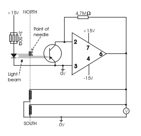
- Construct the circuit as shown in the diagram above, ignoring the compass and iron bar for the moment.
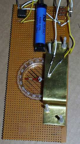
- The LED and the phototransistor (PT) must be exactly aligned vertically, with a separation of 4cm. We used a piece of brass for this but clear perspex is ideal. The compass must fit inside this and you need to be able to see to align the tip of the compass with the LED and PT.
- The coil is actually two coils, set up in parallel by connecting diagonally opposite legs of the reed coil.
- The emitter of the phototransistor should be connected to the zero-rail and the collector to pin 2 of the op-amp.
- Double check your circuit and turn on the power supply. Check that the output voltage at pin 6 of the op-amp is greater than 13V, as the photocurrent through the transistor will be at a maximum. Blocking the light from the LED should reduce this voltage to less than 0.5V.
- Switch off the power and place the compass between the LED and phototransistor. The whole construction should be oriented so that when the compass needle points in an East-West direction it will cut off part of the light beam, preferably as far out on the tip as possible.
- Align the solenoid North-South, 50mm from the needle tip. Secure this with some tape. Turn the power on again, the needle should turn from its ‘North’ position.
- Slowly insert the iron bar into the solenoid. The needle will turn and cut into the light beam. This is where the needle needs to be, and the output voltage should decrease to somewhere in the middle of its range of 15V. Do not move the iron bar or coil once you are happy with their position.
- If the needle did not 'catch'in the light beam try removing the iron bar and turning the coil around to reverse the polarity of the field.
- If the needle oscillates in the beam and doesn't stop, try increasing the distance between it and the coil.
- When you switch the power on at the beginning of a recording, the needle may not position itself properly, in which case a slightly magnetic screwdriver may be used to pull it into the beam to be 'caught' again.
- When taking measurements the magnetometer should be housed in a box well separated from the power supply and voltmeter. The box will also cut out external light.
- The magnetometer readings are those of the voltmeter. To produce continuous readings, a datalogger can be used, or a voltmeter attached to a computer with datalogging capabilities. Automated readings should be taken every 10 seconds.
The output should vary by 0.2V on a quiet day and a range of 1V should be fine for all but the largest geomagnetic storms. Set-up the compass detector away from power cables, electrical equipment and moving metal objects such as lifts or cars. 
|
|
Last Updated ( Monday, 03 October 2022 )
|


 Aurora Watch Website. Version 1.0.